


Файл:Crystodyne oscillator circuit.png
Crystodyne_oscillator_circuit.png (636 × 391 пкс, размер файла: 10 КБ, MIME-тип: image/png)
Описание
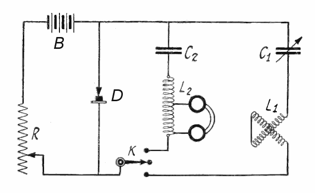
| Описание | Schematic diagram of a "Crystodyne" negative resistance zinc oxide point-contact diode oscillator invented by Russian scientist Oleg Losev in 1923, published in an American radio magazine. Losev used zinc oxide diodes to build the first semiconductor amplifiers and negative resistance devices, which he used to construct solid state radio transmitters and regenerative and superheterodyne radio receivers, 25 years before the invention of the transistor. However Losev's achievements were overlooked because of the popularity of vacuum tube technology, and were forgotten until they were rediscovered in recent decades. This is the schematic diagram of the oscillator shown in Crystodyne zincite oscillator - top.png and Crystodyne zincite oscillator - side.png, built by Hugo Gernsback in New York to Losev's instructions. It can produce radio frequency output up to a few megahertz. The active device is the "cat's whisker" diode D, consisting of a crystal of zincite (zinc oxide) with its surface lightly touched by a steel wire on an adjustable arm. It is biased into its negative resistance region by a DC voltage of 4 - 30 volts applied by battery B and potentiometer R. The negative resistance of the diode excites oscillation in the series tuned circuit, consisting of capacitor C1 and variometer inductor L1. Before operation, a sensitive contact point must be found on the surface of the crystal. To do this switch K is turned to the upper position, which switches a second tuned circuit in, L2 and C2 which oscillates at audio frequency. The wire is dragged across the surface of the zincite crystal until a tone is heard in the earphones, indicating the oscillator is working. Then switch K is turned back to the lower position, switching the RF tuned circuit in. The component values from the source are R = 3 kΩ, L1 = 5 mH, C1 = 10 pF, L2 = 1 H, C2 = 2 mF. With these values the frequency of oscillation is approximately
|
|---|---|
| Источник | |
| Время создания | |
| Автор или правообладатель | |
| Другие версии файла | — |


}=2.3\;{\text{MHz}}}" aria-hidden="true" class="mwe-math-fallback-image-inline" src="https://wikimedia.org/api/rest_v1/media/math/render/svg/baf81a6f3ec5ad9cdda7299896ff2f8d5ce8d819" style="vertical-align: -3.171ex; width:27.843ex; height:7.509ex;"/>
Caption: "Diagram of the oscillating crystal circuit. As can be seen, the hookup is similar to an arc transmitter." Alterations to image: Added labels B and D | источник = Retrieved August 20, 2014 from "The Crystodyne Principle" in Radio News magazine, published by Experimenter Publications, Inc., New York, Vol. 6, No. 3, September 1924, p. 294, fig. 1 archived on American Radio History website | время создания = 1924-09 | автор = Hugo Gernsback — Лицензия: Public domain (в общественном достоянии) }} Источник файла — сайт Wikimedia Commons, куда он был загружен под одной из свободных лицензий ( https://commons.wikimedia.org/wiki/File:Crystodyne_oscillator_circuit.png ). Авторов, работавших над этим файлом см. в истории файла: https://commons.wikimedia.org/w/index.php?title=File:Crystodyne_oscillator_circuit.png&action=history


В общем случае в статьях энциклопедии Руниверсалис файлы используются в соответствии со статьёй 1274 Гражданского кодекса Российской Федерации.
История файла
Нажмите на дату/время, чтобы увидеть версию файла от того времени.
| Дата/время | Миниатюра | Размеры | Участник | Примечание | |
|---|---|---|---|---|---|
| текущий | 12:54, 4 октября 2023 | | 636 × 391 (10 КБ) | Я, робот (обсуждение | вклад) | == Описание == {{Изображение | описание = Schematic diagram of a "Crystodyne" [https://en.wikipedia.org/wiki/negative_resistance negative resistance] zinc oxide point-contact [https://en.wikipedia.org/wiki/diode diode] [https://en.wikipedia.org/wiki/electronic_oscillator oscillator] invented by Russian scientist [https://en.wikipedia.org/wiki/Oleg_Losev Oleg Losev] in 1923, published in an American radio magazine. Losev used zinc oxide diodes to build the first [https://en.wikipedia.org/wik... |
Вы не можете перезаписать этот файл.
Использование файла
Следующий файл является дубликатом этого файла (подробности):

- Файл:Crystodyne oscillator circuit.png на общем хранилище
Следующая страница использует этот файл:
